Squirrel: A Wi-Fi Lighting Control Project
Squirrel lighting controller utilizes Wi-Fi microcontrollers to vary the color and brightness of multiple Wi-Fi-enabled LED light bulbs. The system exposes numerous control commands via Serial (at the access point node), via a TCP/TelNet client, and via an Android app. Various nodes exist for collecting data from the environment, allowing for intelligent modes such as automatic temperature and brightness adjustment.
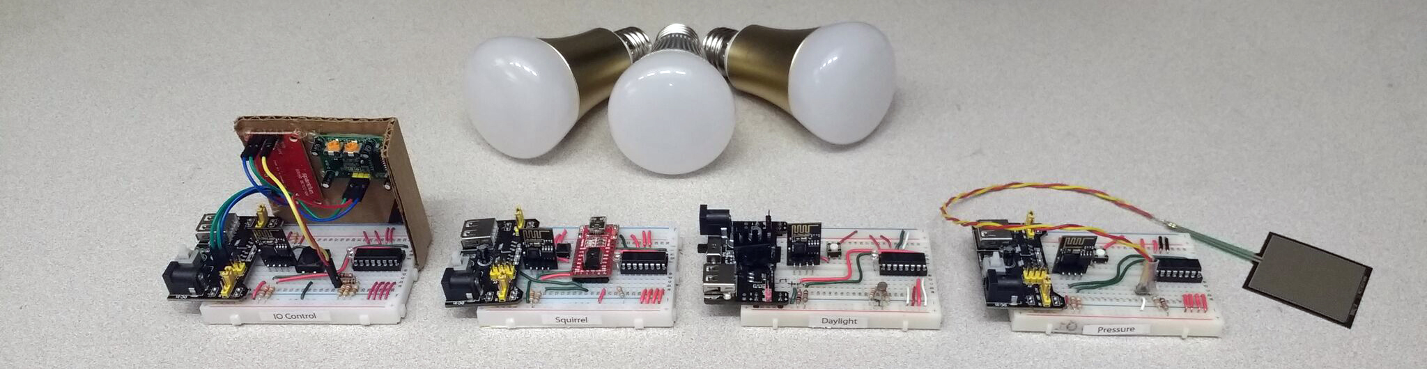
A promotional photo of the prototyped ESP8266 and ESP8285 wireless nodes.
Contents
Features
Commands listed here may be executed from a serial or TelNet terminal. Many of them also have a matching user interface in the Android app.
RGB Color
The user may set or get the bulb's 24-bit color, or specify the automatic color wheel sequence. The color wheel
sequence varies the hue while holding full saturation, and using the user-specified brightness level. These settings
can be changes by executing the color R G B command or get-color.
Color Temperature
The user may set or get bulb color temperature, which is an 8-bit value from 0 (warm) to 255 (cool). Lights which
feature warm and cool LED channels will proportion power between them. Bulbs without these dedicated channels will
emulate the desired temperature using the channels they have available. An automatic mode is available for setting
temperature based on exterior daylight levels. The command for this is temp 0-255/auto
or get-temp.
Listen/React Mode
The user may enable audio listen mode, which pulses lights and changes their colors based on audio input. This system
is designed to detect significant spikes in audio intensity and triggers the color change and pulse at those times.
This may be described as "party mode." The command for this is listen.
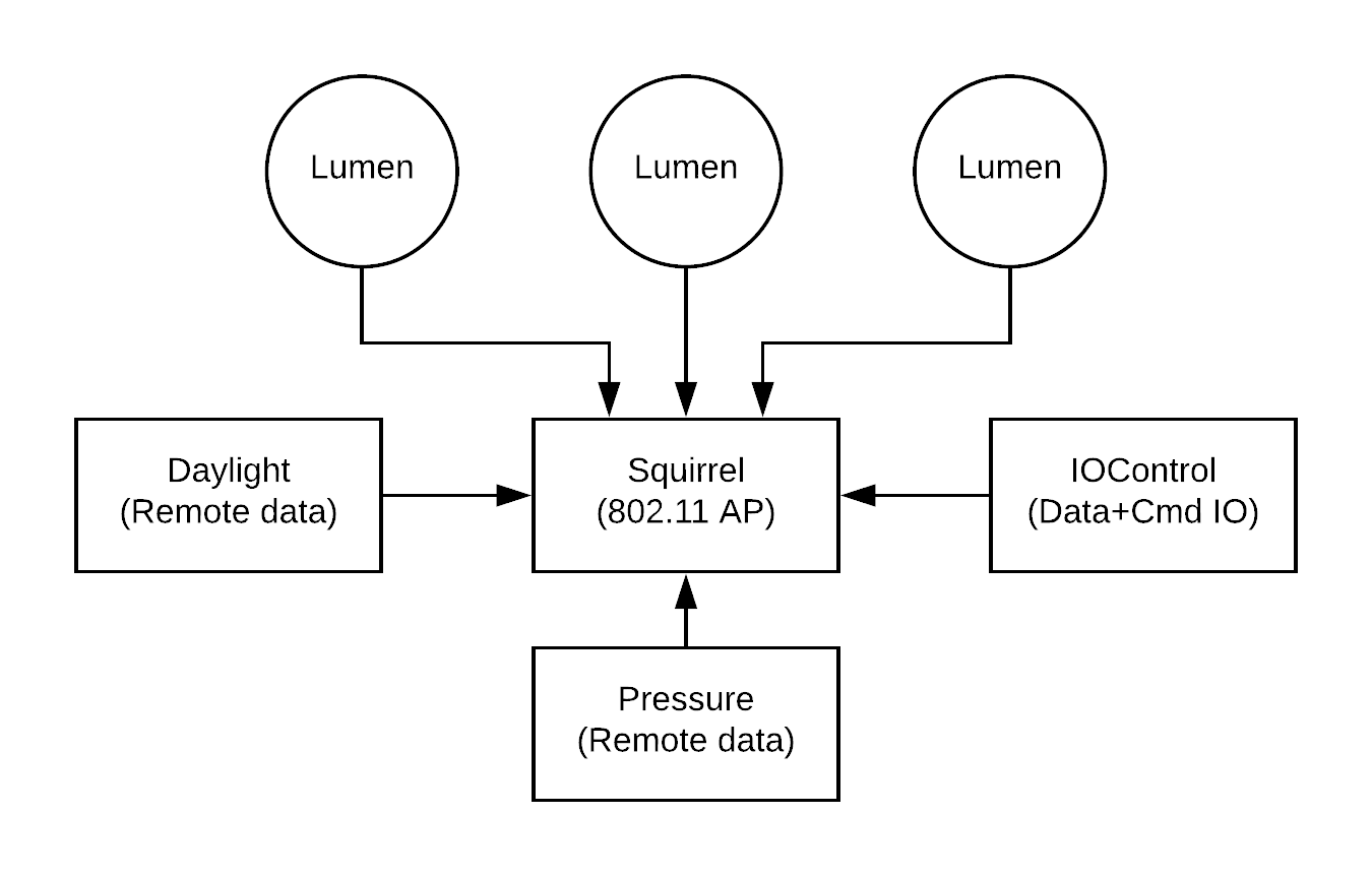
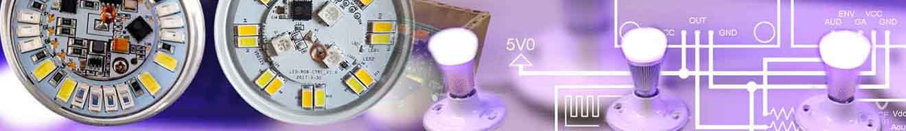
Demonstrates three lumen nodes receiving data from the controller in listen mode.
Motion Power Saving
The user may enable or disable a motion sensor timeout feature, and set the timeout duration. The motion sensor
hardware will add about 5 seconds to this duration. The command for this is motion on/off/seconds
or get-motion.
Clap On, Clap Off
The user may enable or disable a clap-on and clap-off feature. When enabled, two successive claps will power off the
light, or resume its last active state. This mode is automatically disabled when using listen mode, described below.
The command for this is clap on/off or get-clap.
Brightness
The user may set or get an 8-bit brightness level. This will scale down an RGB color or temperature. Alternatively,
the user may set an automatic brightness, where a pressure sensor underneath a matress or seat cussion triggers all
lights to dim to half brightness. The command is brightness 0-255/auto or get-brightness.
Hardware
All nodes except the Sonoff B1 bulb use the Espressif ESP8266EX chip for logic and wireless communication. While the light nodes use this chip directly, the other nodes use the ESP-01 on a prototype breadboard.
Access Point
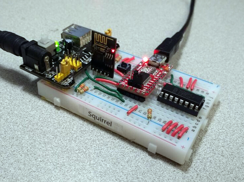
A view of the Wi-Fi access point and user communication controller.
This node uses an ESP-01 module to create a Wi-Fi access point. The access point is private, and this keeps the network secure. It is important to note that the communication protocols are not secure, and that the secure access point prevents this from being a problem.
The access point, called "Squirrel" has a few important roles besides being the network switch:
- Stores hostname entries for each node
- Exposes user commands via USB Serial (FTDI) at 9600 baud
- Exposes user commands via TCP/Telnet port 23
- Exposes user commands via TCP to the Android application
- Captures and displays remote diagnostic messages via USB Serial
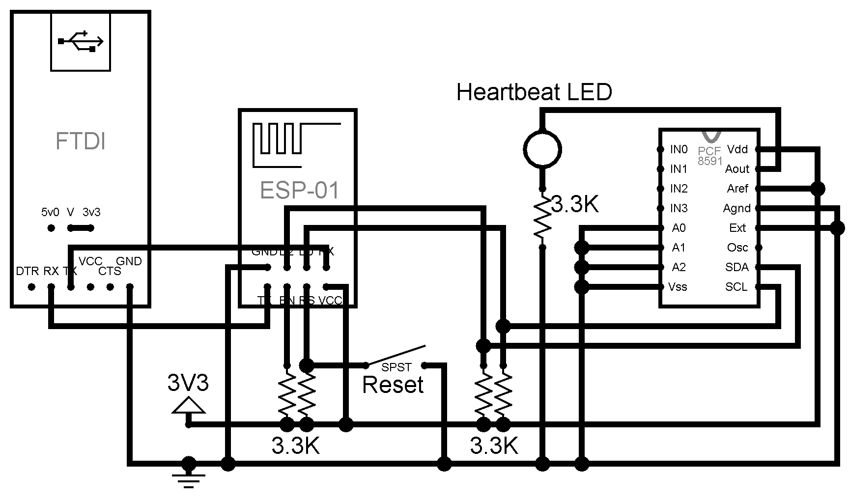
A circuit view of the wireless access point.
IO Controller
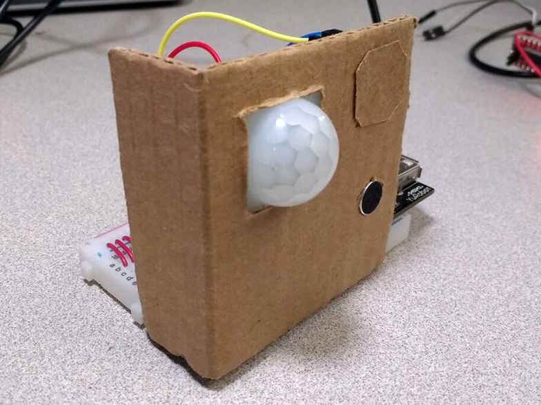
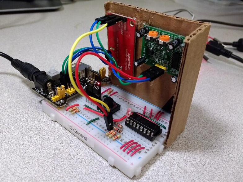
Two views of the data IO controller node.
This node uses an ESP-01 module to connect to the access point. Data is harvested from the two onboard sensors: the SparkFun Audio Detector and the PIR motion sensor. The audio detector is used because it provides an approximate envelope, which attempts to wrap the amplitude of the incoming waveform. This is necessary because we cannot sample raw audio data fast enough to reliably interpret the waveform.
This node also connects to the remote nodes, Pressure and Daylight, to read their sensor data. Information from all four of the sensors is used to determine various states, depending on the user-defined operating mode. For example, in the audio reaction (listen) mode, the audio sensor's spikes are used to change the color and brightness of the lights to produce a rave-like effect.
The roles of IO Control are:
- Handles user commands proxied from the access point
- Connects to remote sensor nodes
- Collects local and remote sensor data
- Watches for new lights on the network
- Streams light data to subscribed light nodes
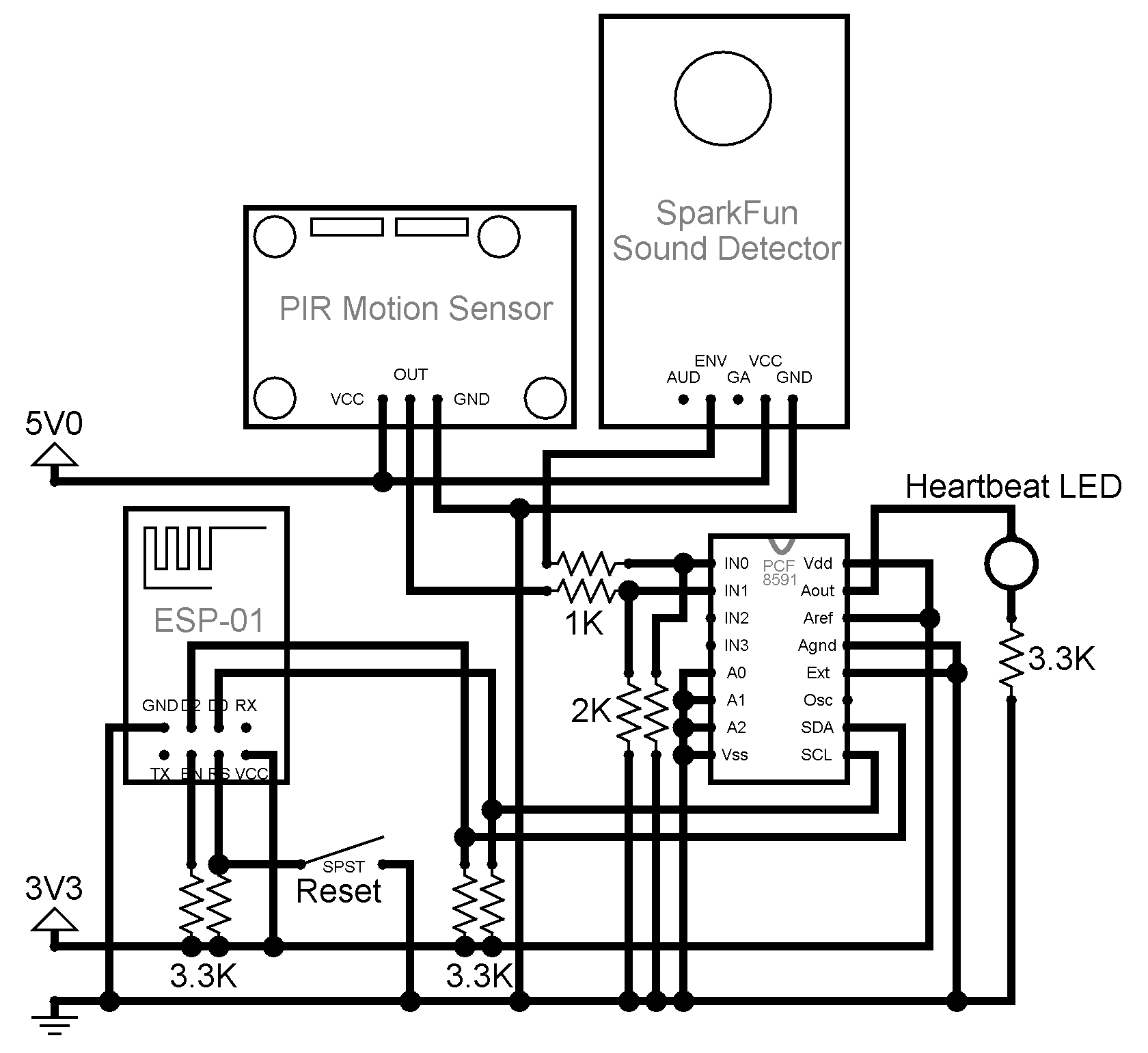
A circuit view of the IO controller node.
Remote Data Collection
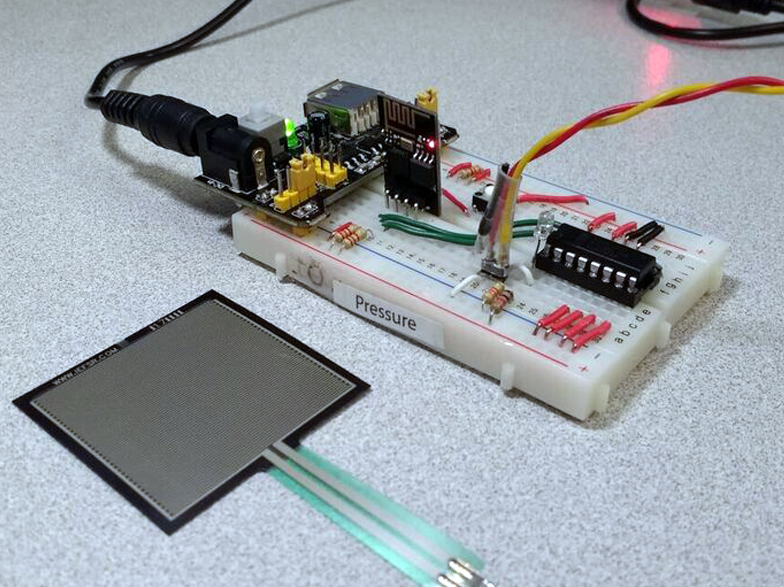
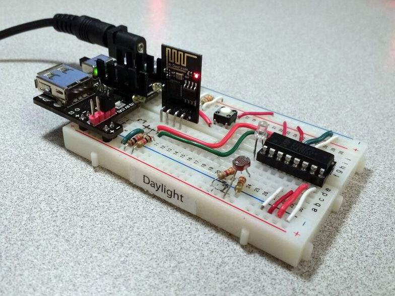
A view of the Pressure and Daylight sensor acquisition nodes.
These nodes use an ESP-01 module to connect to the access point. Data is harvested from either a photoresistor or a resistive pad. The data is collected on demand of a remote node over a dedicated connection.
The roles of Pressure and Daylight are:
- Respond to query commands
- Collects local sensor data
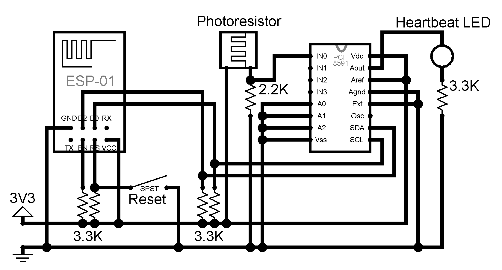
A circuit view of the Daylight acquisition node.
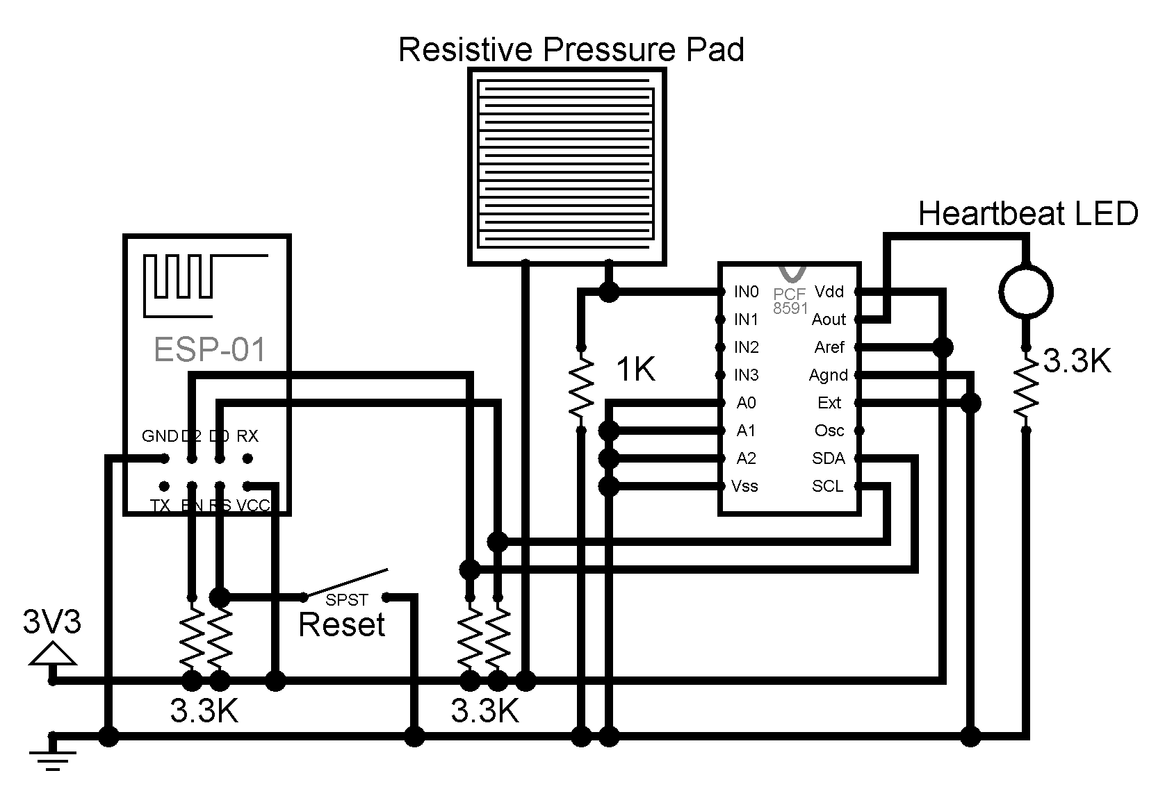
A circuit view of the Pressure acquisition node.
Lights
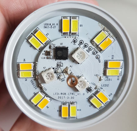
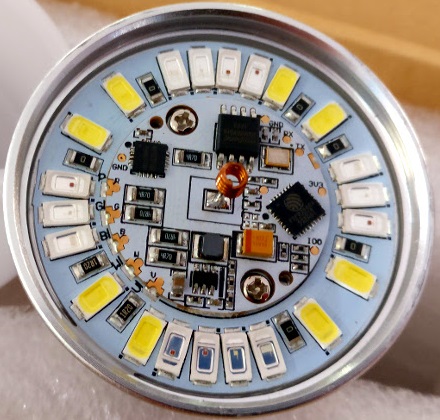
A view of the Wi-Fi LED bulbs. Sonoff B1 (first) and Thinker AILight (second)
These nodes use an ESP8266EX or ESP8285 to connect to the access point. Upon successful connection, they wait for light data. The data they received is transmitted on 2-wire to an LED driver chip, or a chain of two LED driver chips.
The roles of Lumen (light) nodes are:
- Notifies IO Control to be discovered
- Receives light color or temperature instructions
- Updates LED drivers accordingly
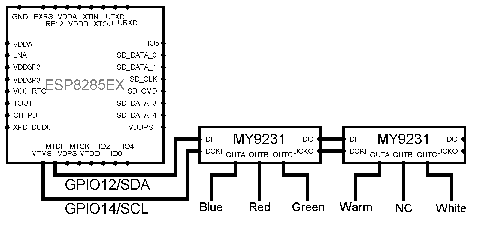
The important circuit connections for the Sonoff B1
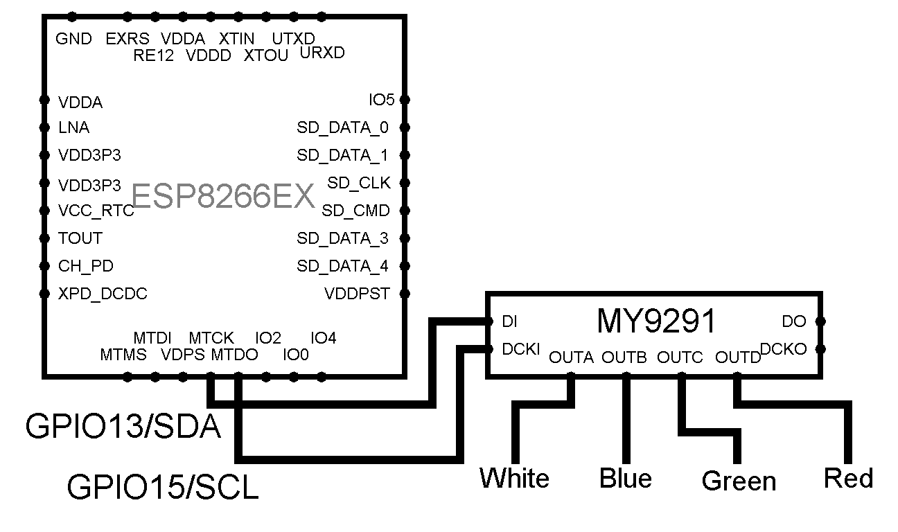
The important circuit connections for the Thinker AILight
Networking
There are four major parts to the inter-node communication.
The first is the 802.11 Wi-Fi connections. The Squirrel access point opens with a pre-defined SSID and password. Each node knows these credentials, and connects to it upon startup or reset. Each node stalls all logic functions until a connection is made, which can be observed when the heartbeat LED stops flashing on any control node. Most importantly, this connection logic helps to synchronize nodes. When the access point is reset, it powers off the radio for one second, signalling other nodes to destroy any open connections and enter the connecting state.
The Wi-Fi connections between network nodes.
The second part to inter-node communication is hostname registration. Each control node opens a TCP connection to a "TCPClientRegistrar" instance running on the access point. Since the access point has the static IP of 1, each node can find it without discovery. The access point will ask each registering node for its identity, and will populate a table of IP address and hostname pairs. Why is this necessary? Nodes can connect to the AP in any order, which means a bulb could grab the address 2 before a node comes online with that static IP. This creates a conflict. The issue is resolved with this DNS-like approach.
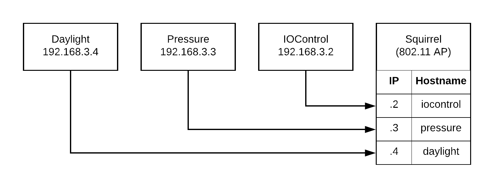
The hostnames as each node will register them.
The third part is establishing control connections between nodes. Due to reliability problems with TCP on the 8266 WiFi library, these are established using UDP wrapped as a stream class. The stream is used so that a common command interpreter class may handle incoming requests on Serial, TCP, and UDP without specialized code. Since UDP is packet based, we use flush() to force a packet to be sent out. A special sync packet is used between nodes to reset sequence numbers, which ensure ordered delivery and relevance of responses. To get connected, each node must know ahead of time which hostname and port it wants to establish a connection on. Using Squirrel (access point) and IO Control as an example, Squirrel fetches the IP address of IO Control from the registrar, then connects to IO Control at that address. IO Control is already waiting for the connection and sync instruction.
There are four of these control connections active once the system has fully synchronized:
- Squirrel --> IO Control: User commands are proxied
- IO Control --> Squirrel: Hostnames are resolved
- IO Control --> Pressure: Pressure data is retrieved
- IO Control --> Daylight: Daylight levels are retrieved
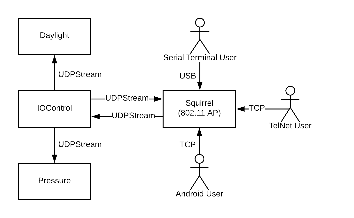
The communication command channels between nodes.
Our fourth and final part to the communication is the data being sent to light nodes. Each node boots up like the control nodes, first connecting to the access point. However, there are no hostnames here, since the number of bulbs are unknown. Instead, each node begins broadcasting a discovery packet. IO Control listens for these packets, and adds the source IP addresses to a subscription list, so that the bulb will begin receiving data packets in a multicast. The multicast runs at 30 frames per second from IO Control to all subscribed lumen nodes when the main loop is not blocked on a connection task. This is the only connection in the system that is simplex.
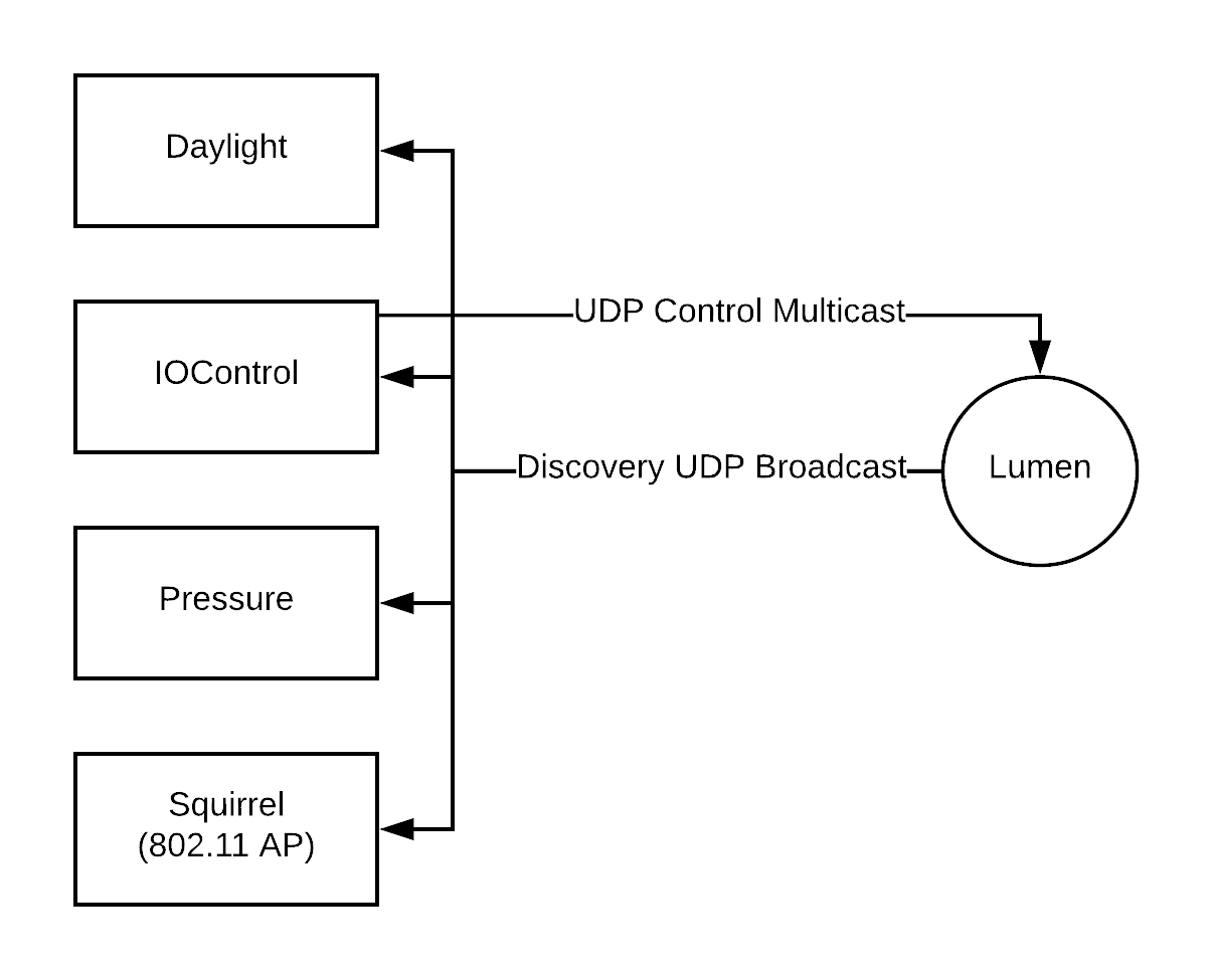
The simplex data channel and discovery from iocontrol to each lumen node.
Next Steps
There are many parts of this design that could use improvement, particularly those involving the user interface presented by the mobile application. There is also plenty of room to add security to allow for access point pairing, so that a more scalable network may be utilized.
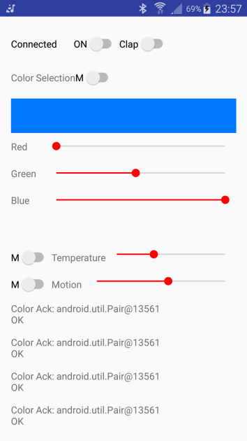
The current Android user interface.
The current network with an ESP8266 as the access point presents a technical limit of 8 lights. This is because the access point only allows 12 connections, 4 of which are used by the control nodes. Sources suggest this can be raised to 16, but tests were unsuccessful with the current version of the library. Using a dedicated wireless router or switch would quickly solve this problem.
Full Command Reference
To retrieve this list, execute the help command at the user terminal.
User Commands:
- color [R G B]/[auto] Sets color or auto
- get-color ........... Gets last set color value
- temp [T]/[auto] ..... Sets temp or daylight auto
- get-temp ............ Gets the last set temp value
- brightness [B]/[auto] Sets brightness level
- get-brightness ...... Gets the last set brightness
- clap on/off ......... Sets clap power control state
- get-clap ............ Gets last set clap state
- power on/off ........ Manually power on/off
- get-power ........... Get last set power state
- motion time/on/off .. Set motion timer
- get-motion .......... Gets motion state
- get-mode ............ Gets system mode
- listen .............. Enables audio react, disables clap
- get-debug ........... Gets all sensor data manually
Advanced Commands:
- ip .................. Get IP by identity
- identify ............ Get server identity
- help ................ Command syntax manual
- test-args ........... Test argument parser
- set-timeout ......... Connection command timeout
- get-stats ........... Get send/recv counters
- drop-remote ......... Kill remote connections
Build It Yourself
Difficulty: Difficult
Knowledge required: Soldering iron experience, electronics handling and language, Arduino
Tools: Soldering iron, hot glue gun
| Item | Cost | Source |
|---|---|---|
| PIR Motion Sensor | $2.84 USD | eBay |
| Force-sensitive Resistor | $9.95 USD | SparkFun |
| 4x 400 point breadboards | $7.99 USD | Amazon |
| Photoresistor Cell | $0.95 USD | Adafruit |
| 4x MB102 breadboard power supplies | $16.00 USD | Amazon |
| 1x ESP8266-based WiFi Light (AILight) | $14.66 USD | eBay |
| 4x ESP-01 boards (unsoldered) | $16.00 USD | eBay |
| SparkFun Sound Detector | $11.95 USD | Amazon |
| At least 3X PCF8591 or equivalent analog input chips | $5.00 USD | eBay |
| FTDI232 USB 3.3v Serial | $2.19 | eBay |
| L-shaped Leads/pins for ESP-01 | N/A | N/A |
| Breadboard leads, male-male, male-female | N/A | N/A |
| SPST buttons | N/A | N/A |
| Solder | N/A | N/A |
| Hot glue | N/A | N/A |
| Various resistors (see circuits) | N/A | N/A |
| Decoupling capacitors, if you want to be smarter than me | N/A | N/A |
The parts presented here are for all four control nodes, and one light bulb.
Assembly
Once the parts are obtained as listed above, the assembly should match the circuit designs presented earlier in this document. If you cannot solder, or if you cannot understand the circuits listed above, I highly recommend starting on a project that is less expensive. Understanding the dangers of electrostatic discharge is important when working with the ESP8266.

Programming
To assemble this network, you will need to be familiar with programming ESP devices, including the light bulbs. A supplemental article may eventually be added to this site and linked here. Our Git readme file also provides a very quick explanation.
All of the code for this project is currently present in a Git repository, which you are welcome to fork and contribute to. This repository is still living, and updates to code and documentation over time should be expected.
Squirrel Lighting Control on GitHub
Library and module descriptions:
- sketch_esp8266_node_daylight: The daylight remote sensor node
- sketch_esp8266_node_iocontrol: The IOControl node
- sketch_esp8266_node_lumen: Each light node
- sketch_esp8266_node_pressure: The pressure remote sensor node
- sketch_esp8266_node_squirrel: The access point and server node
- Libraries/ESP8266-CommandInterpreter: Interprets incoming commands, invokes unix-style handlers
- Libraries/ESP8266-TcpClientRegistrar: Registers hostnames to IP addresses, can also create persistent connections
- Libraries/My9231: 3-channel LED driver, wraps the My9291 4-channel LED driver
- Libraries/PCf8591: A/D D/A converter chip driver on I2C
Credits
This project was initially developed for CSS 427 Embedded Systems at the University of Washington | Bothell. This was a student project between myself and Stanley Mugo, Computer Science and Software Engineering.
If you have any questions regarding this project or steps taken to create or expand it, please contact me.
Published: 12/21/2017 21:59 PST
Modified: 12/22/2017 11:30 PST
Article URL: http://www.bitfracture.com/pages/techarticles/squirrel-esp8266-esp8285-wifi-lightbulb-control-project
Website Title: Bit Fracture Online
Website URL: http://bitfracture.com
Media Type: Documentation
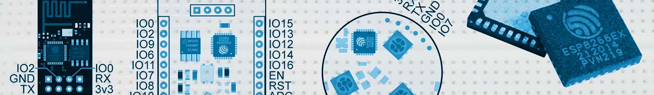 The ESP8266 and ESP8285 can run your Arduino code directly, in many cases with more program space, more RAM, and a faster CPU.
 Squirrel lighting controller utilizes Wi-Fi microcontrollers to vary the color and brightness of multiple Wi-Fi-enabled LED light bulbs.
 Is the volume adjustment stuck or faulty on your Ford radio? This is a technical guide to a potential fix.
 This article covers how to take multiple bootable ISO images and create a single bootable USB key for all of them.
 Are you sick and tired of IDEs? This tutorial will show you how to configure Notepad++ macros to compile your code, so you can ditch big IDEs forever.
 This article is the hub for my collection of classic computers. From this page you can see the story behind each of my systems, their specifications, screen shots, and more.
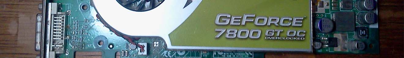 The NVidia GeForce GT 7800 has an issue with its cooling fan circuitry that causes it to get stuck at max speed. This article covers removing a faulty transistor from the device to circumvent this issue.
 Are you tired of the painful speed of Windows Vista? This article covers a number of simple ways to improve your desktop performance.
 This article explains the game that everyone seems to be talking about, Minecraft.