Programming ESP8266 And ESP8285 With Arduino IDE
Many developers incorrectly assume that an ESP-01 or equivalent module is a peripheral component for an Arduino or other microcontroller. While it may ship from the factory this way, it can do so much more. The ESP8266 and ESP8285 can run your Arduino code directly, in many cases with more program space, more RAM, and a faster CPU.
Contents
Introduction
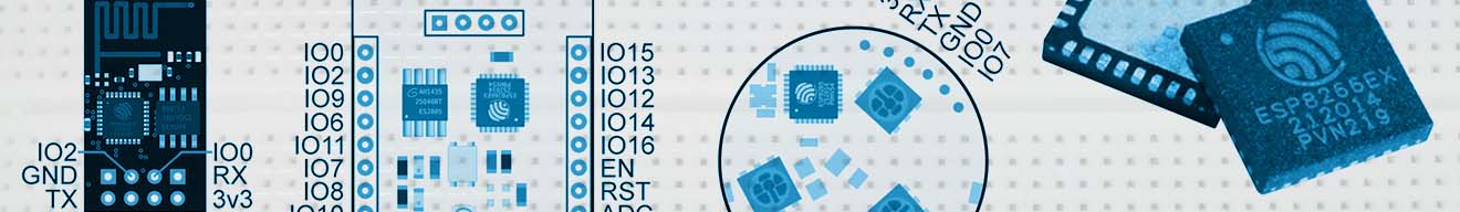
ESP8266 and ESP8285 chips are very popular among electronics hobbyists and manufacturers. What makes them so attractive is their size, speed, and programmability. The chip itself is surface-mount, giving it an impressively small footprint. With an antenna, an ESP8285 is a fully-functional 802.11 wireless microcontroller. Add a flash chip, and an ESP8266 is too.
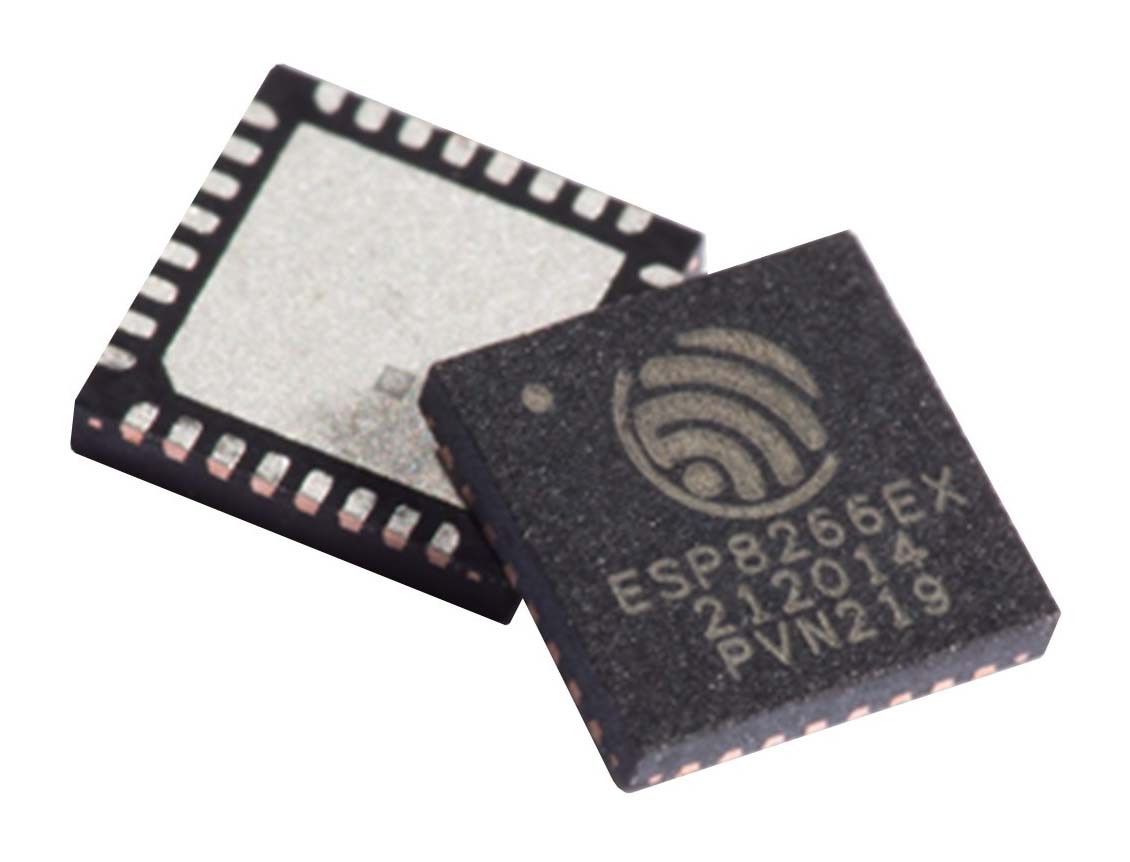
Figure 1: The ESP8266EX wireless microcontroller.
There is quite a selection of pre-baked boards, many of which can be plugged directly into an IoT project. The boards I have had the chance to interact with include the ESP-01 module, ESP-201 module, and Sonoff B1 wireless lightbulb. Figure 2 shows the interface of these boards, where a varying set of pins are exposed.
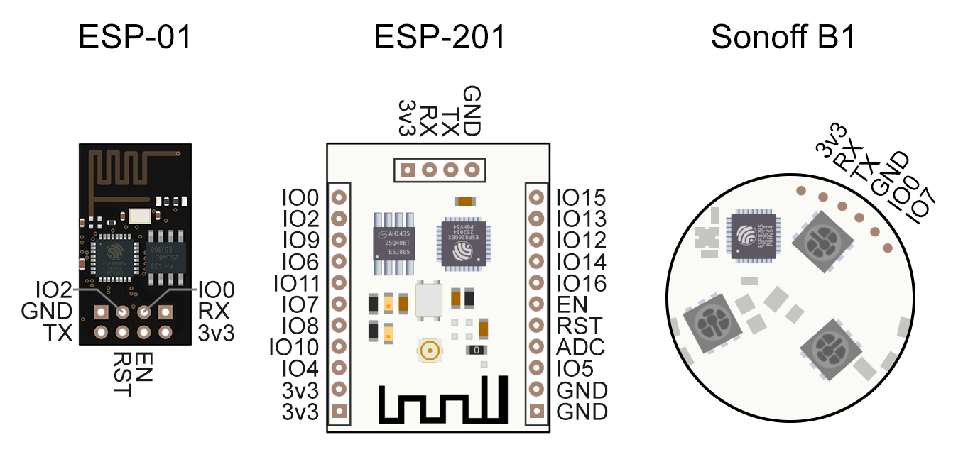
Figure 2: Three ESP boards which expose differing sets of pins.
Preparation
- Acquire an ESP8266 or ESP8285 board
- If your ESP board does not have a USB port...
- Confirm that the board exposes RX, TX, Ground, and IO0 as a pad or pin
- Acquire a 3.3v USB-serial board (such as FTDI)
- If your ESP board does not have a built-in power supply...
- If you have a dedicated USB line, use a 3.3v regulator for power.
- Or, acquire a 3.3v DC power supply for powering the module
- Acquire a solderless breadboard for easy circuit prototyping
- Acquire some resistors of 3K ohms or greater for input pull-up
- Acquire some breadboard leads for circuit prototyping
- Download and install Arduino IDE from Arduino.cc
Hardware Setup
Pins and Pads
Discover how to get power and data to your device. If you have through-hole pads, consider soldering pins onto them first. When using the ESP-01 with a breadboard, you may consider L-shaped pins as shown in Figure 3. Notice that the pins on the back of the board (the flat side) are coming from the lower holes, and the front pins go to the higher holes. This is recommended in order to match the silkscreen pin labels and avoid confusion that may cause you to burn out your board.
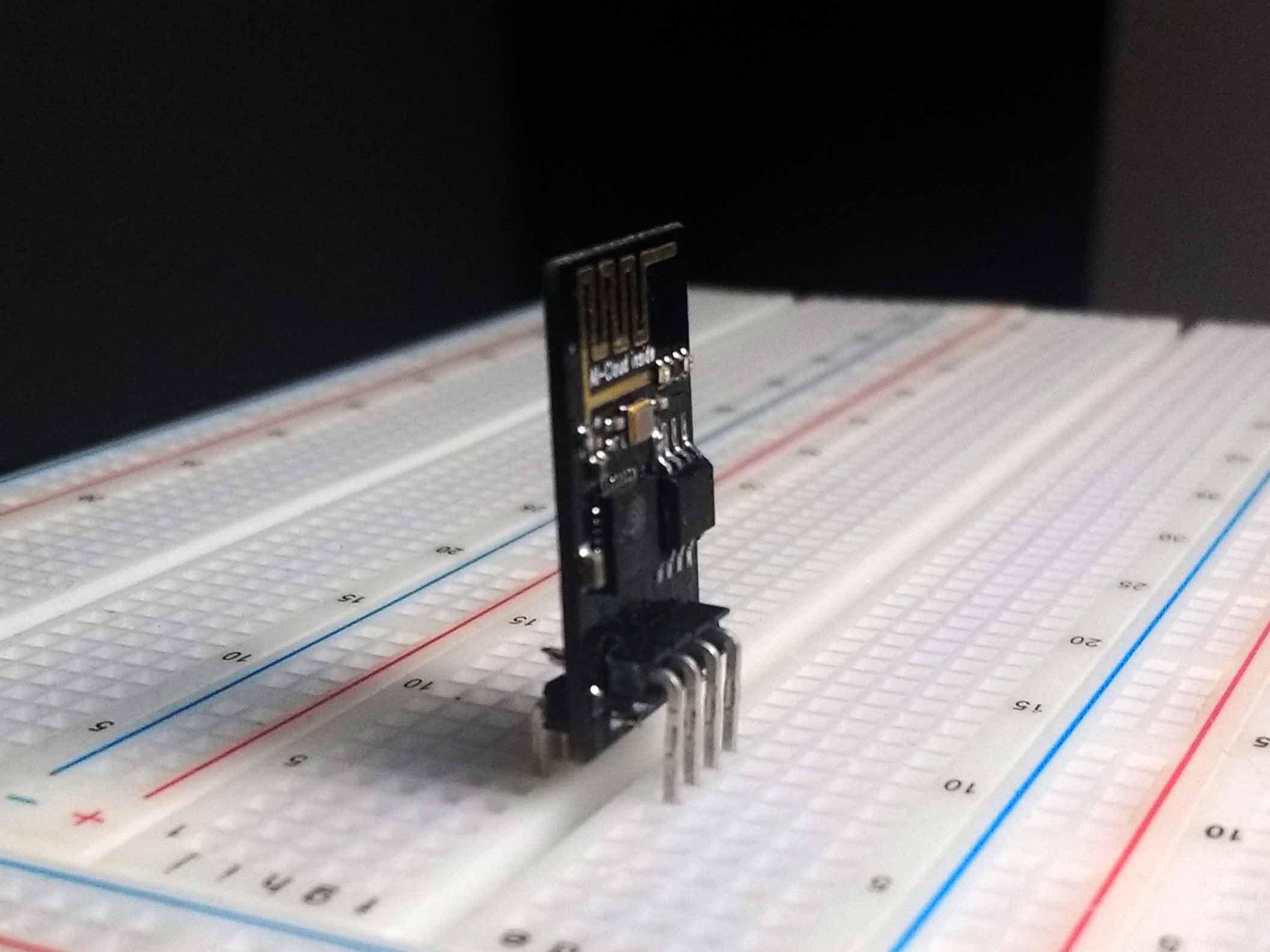
Figure 3: ESP-01 with L-shaped pins for breadboard compatibility.
If you are using an ESP-201 board, note that the serial access headers are not parallel to the other pins. Consider mounting these pins facing upwards so that your device will plug into a breadboard.
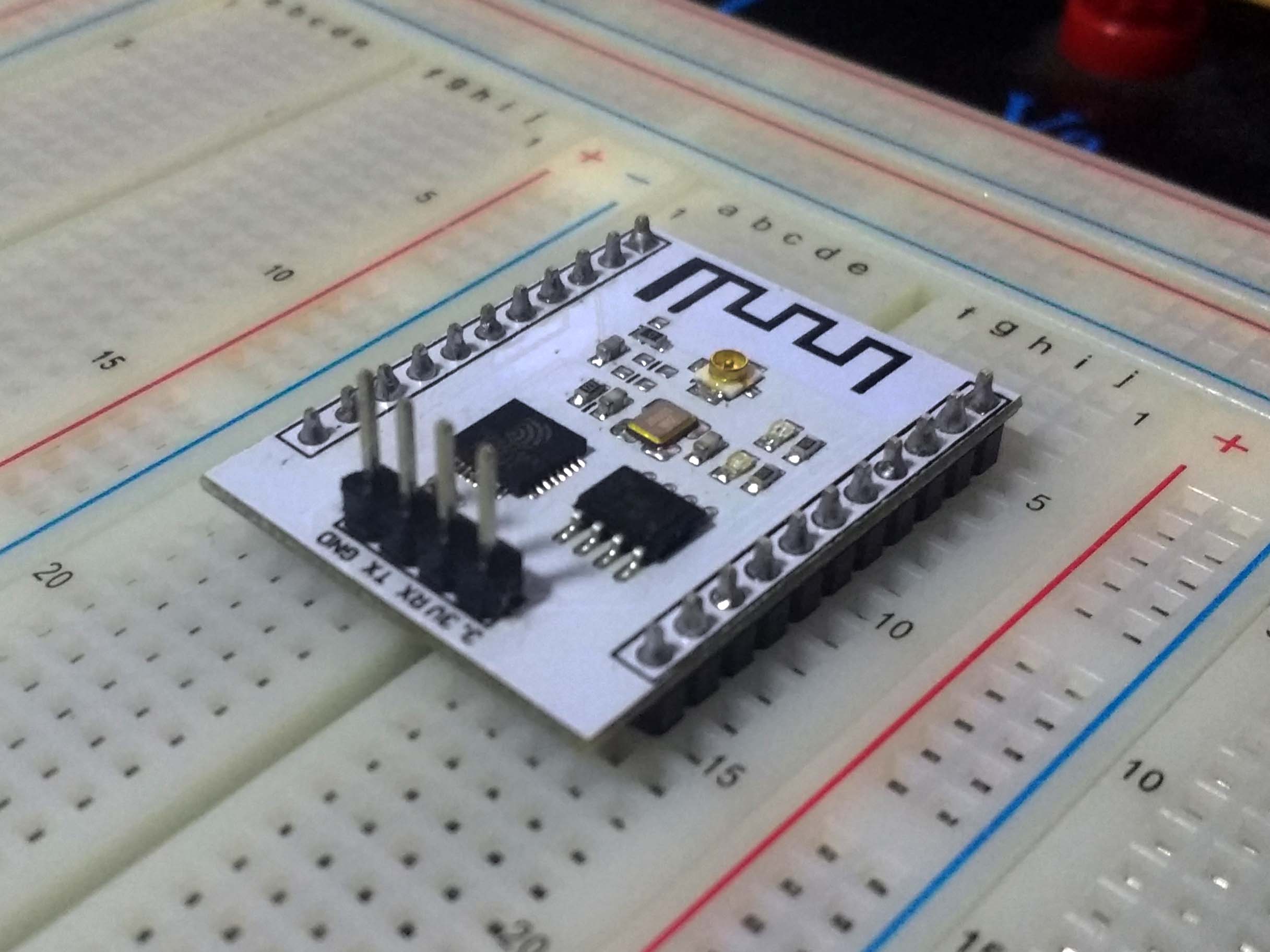
Figure 4: ESP-201 with breadboard compatible serial pins.
If you are using a surface-mount board such as the ESP-12 or many others, consider an adapter board, as shown in figure 5, or building your own adapter using protoboard and angled leads. Note that this adapter should not place metal behind the antenna, or it may block the Wi-Fi signal.
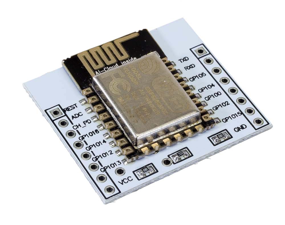
Figure 5: ESP-12 with a breadboard compatibility adapter.
If you are using a Wi-Fi lightbulb such as the Sonoff B1, be very careful with the surface pads it exposes. If you solder a pin, the stress of the lead can break the pad off. The solution I found involves hot gluing a row of three pins to the circuit board, then running fine wire leads from the pins to the surface pads. This way, the pins can flex and even break off, and the thin wire should avoid transferring this force to the pads. Using garbage bag twist ties can work, but you need a lot of gel flux to clear away the oxidation.
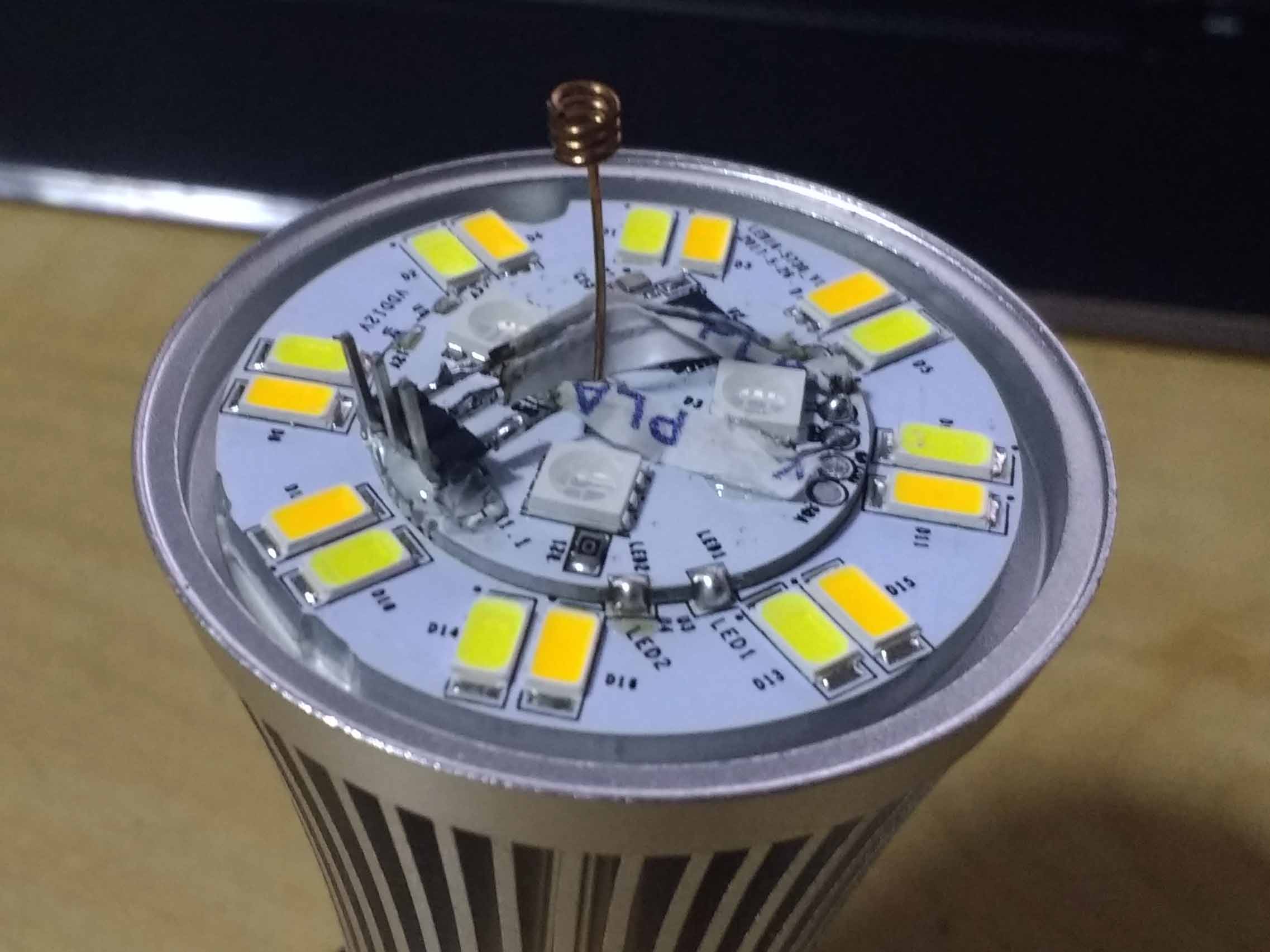
Figure 6: Sonoff B1 with low-strain pins added.
Powering Your Board
It is rhumored that at maximum current draw, the ESP8266 can pull more power than your computer's USB connection can provide. Some sources claim a peak of around 320mA momentary current spikes. This should be fine for some USB connections, but may not be for others. And if you have any other hardware, such as an Arduino, you definitely want to rely on an external power supply for your ESP board. If you are using a board with its own power supply, such as a wireless lightbulb, this does not apply to you.
You can connect a 3.3v power brick to your breadboard, or buy a voltage regulator that accepts a 5v power brick (or 5v USB power). However, I have had great luck using MB102 breadboard power adapters for my prototyping projects. The big benefits are independence from your USB connection, a wider input voltage range, and multiple output voltages at high amperage. This board typically accepts 7-12 volt power adapters, and puts out 5v and 3.3v at 1 amp. Best of all, they attach directly to a modern breadboard. If you use one of these boards, be sure to fix the power level jumpers in the 3.3v position! Failing to do so may result in a dead or unreliable ESP board, or may damage surrounding hardware.
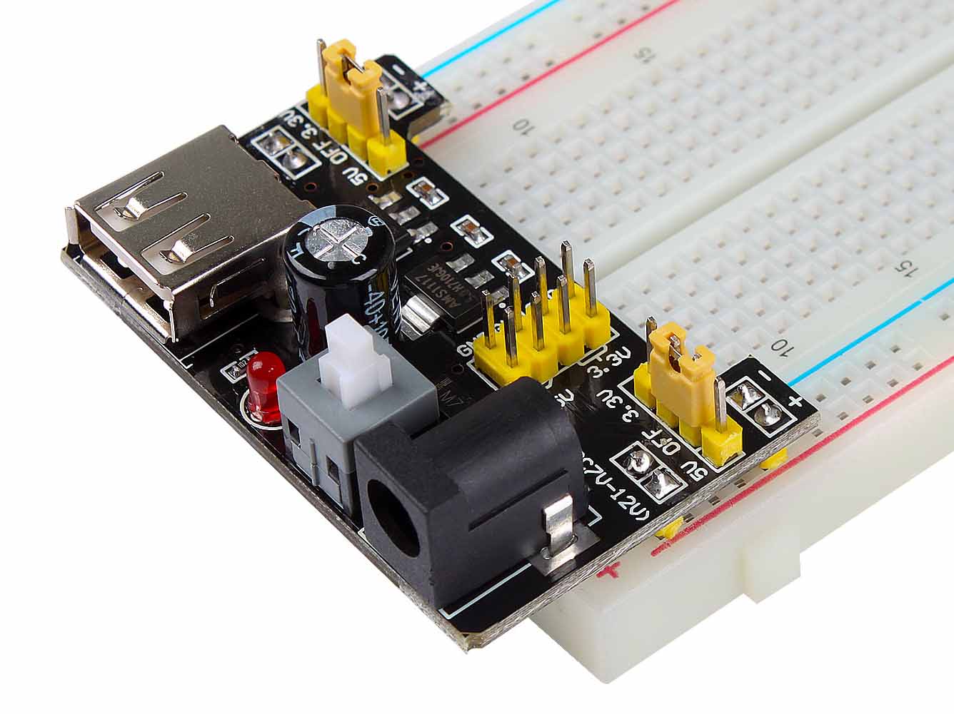
Figure 7: MB102 breadboard power adapter.
To ensure your device runs in a known state, pull RST, CH-PD/EN, IO0, and IO2
to 3.3v through 4 separate resistors. Pull IO15 to ground with a resistor. The
resistors are not mandatory on IO2, IO15, or EN, but are recommended to avoid
unexpected contention that may fry a pin. Any resistance from 3K to 10K is reasonable.
Note that the current wasted by a 3K pull-up, using I = 3.3v / 3000ohms, is around 1.1 mA when the
pin is grounded. Using larger resistors means less wasted power, but a slower
reaction to the signal being changed.
After you have a power supply in place that supplies 3.3v to your breadboard, use leads to connect the ESP's 3v3 pin to power, and the GND pin to ground. If you give power to your board now, you should see an indicator for power or a flashing LED representing serial output from the debug logger. Not all boards have these LEDs available.
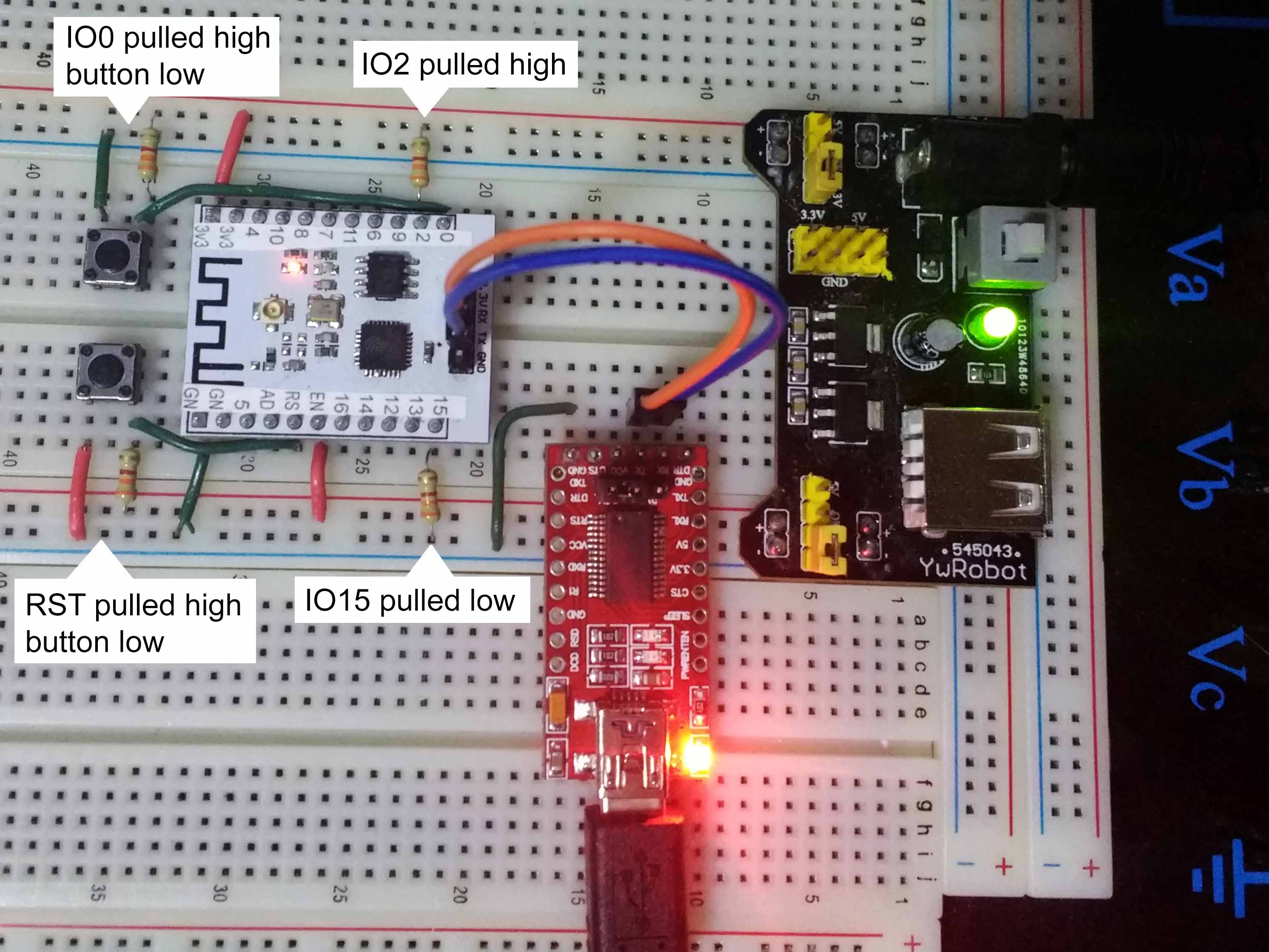
Figure 8: Completed breadboard with ESP-201.
Communication Setup
Next, if you do not have a USB port on your board, use an FTDI or equivalent board to connect to the UART interface. Make sure your FTDI is in 3.3v mode to avoid frying the interface. Reference Figure 8 from the previous section for how this looks.
- Connect the FTDI ground to your breadboard ground
- Connect the FTDI RX to the ESP TX
- Connect the FTDI TX to the ESP RX
To test the connection, open Arduino IDE. You will see a menu option for Tools -> Port. Choose the port your device is communicating through. If you don't know, choose one at a time, send some characters with the serial monitor, and see if your FTDI flashes when you do so.
Set your serial monitor to 74880 baud for this test. The ESP chips send a quick burst of debug information at this rate when they initialize, before your code gets executed. Power on your ESP device and watch the serial monitor. If you see something like this, you are golden:
ets Jan  8 2013,rst cause:2, boot mode:(3,6)

load 0x4010f000, len 1384, room 16
tail 8
chksum 0x2d
csum 0x2d
v3de0c112
~ld
IDE Setup
Open Arduino IDE, and from the menu choose File -> Preferences. Populate "Additional Boards Manager URLs" with "http://arduino.esp8266.com/stable/package_esp8266com_index.json". If you wish to use a specific version of the Arduino libraries for ESP8266, replace "stable" with a version number in that path. Press Ok to close.
Choose Tools -> Board -> Boards Manager from the menu. Search for "esp8266" and install it. Lastly, in the sketch you wish to upload, choose Sketch -> Include Library -> ESP8266WiFi. This library will enable communication with the ESP chip, exposing an interface similar to the official Arduino WiFi shield library.
#include <ESP8266WiFi.h>
#include <ESP8266WiFiAP.h>
#include <ESP8266WiFiGeneric.h>
#include <ESP8266WiFiMulti.h>
#include <ESP8266WiFiScan.h>
#include <ESP8266WiFiSTA.h>
#include <ESP8266WiFiType.h>
#include <WiFiClient.h>
#include <WiFiClientSecure.h>
#include <WiFiServer.h>
#include <WiFiUdp.h>
Choose the correct board by going to Tools -> Board. If your module is not listed, choose the generic option for the chip your module uses. Next, you may choose a different flash size if your hardware features a larger flash. Leaving it smaller than your real flash chip will not cause any problems, but choosing a size too large will result in a corrupted write.
Select verify (compile) to ensure your libraries are included correctly. Compilation may take a minute or two, since the WiFi library and its underlying libraries are rather large. Future compilations within the same IDE session will be faster.
Flashing Your Program
If your board features a USB connection, there is probably a program button on your board as well. When you push code from Arduino IDE, you need to hold this button and reset your board at the same time.
Most ESP boards do not feature programming hardware. If this is the case, you need to ground IO0 and then momentarily ground RST. Note that our pull-up resistors make it really easy for us to add buttons to do this job. The connections are set up like this:
- IO0 is connected to 3.3v through a resistor (3K or more)
- IO2 is connected to 3.3v through a resistor (3K or more)
- IO15 is connected to ground through a resistor (3K or more)
- RST is connected to 3.3v through a resistor (3K or more)
- CH_PD/EN is connected to 3.3v through a resistor (3K or more)
- RST is connected to an SPST button, which is connected to ground
- IO0 is connected to an SPST button, which is connected to ground
This configuration has added a reset and program button to your breadboard. If you don't want to do all of this work, or maybe you don't have a button, you can use a lead to emulate a button each time you program or reset. If you are using an independent power source, you may power cycle the device instead of resetting it. This reduces the work needed to add pins to a Wi-Fi light.
To program your device:
- Press upload in your Arduino IDE
- Hold the program button, or ground the IO0 pin with a lead
- Momentarily press your reset button, touch the RST pin to ground with a lead, or cycle power
- Release the program button
- Wait for the IDE to upload to the board
The programming screen will look something like this:
Uploading 229104 bytes from /.../sketch_dec27a.ino.bin to flash at 0x00000000
................................................................................ [ 35% ]
................................................................................ [ 71% ]
................................................................                 [ 100% ]
If you have any questions regarding this project or steps taken to create or expand it, please contact me.
Published: 12/27/2017 20:32 PST
Modified: 12/27/2017 20:32 PST
Article URL: http://www.bitfracture.com/pages/techarticles/programming-esp8266-esp8285-with-arduino
Website Title: Bit Fracture Online
Website URL: http://bitfracture.com
Media Type: Documentation
 The ESP8266 and ESP8285 can run your Arduino code directly, in many cases with more program space, more RAM, and a faster CPU.
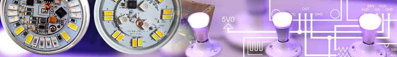 Squirrel lighting controller utilizes Wi-Fi microcontrollers to vary the color and brightness of multiple Wi-Fi-enabled LED light bulbs.
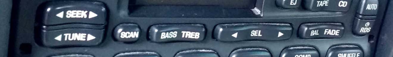 Is the volume adjustment stuck or faulty on your Ford radio? This is a technical guide to a potential fix.
 This article covers how to take multiple bootable ISO images and create a single bootable USB key for all of them.
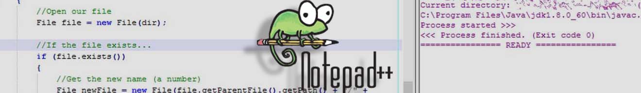 Are you sick and tired of IDEs? This tutorial will show you how to configure Notepad++ macros to compile your code, so you can ditch big IDEs forever.
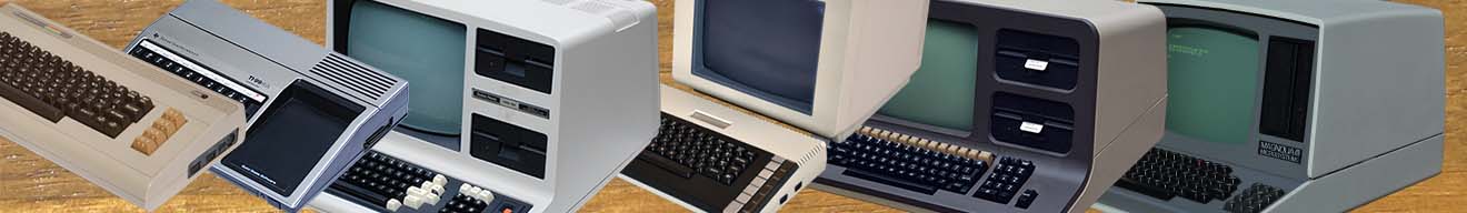 This article is the hub for my collection of classic computers. From this page you can see the story behind each of my systems, their specifications, screen shots, and more.
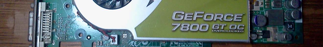 The NVidia GeForce GT 7800 has an issue with its cooling fan circuitry that causes it to get stuck at max speed. This article covers removing a faulty transistor from the device to circumvent this issue.
 Are you tired of the painful speed of Windows Vista? This article covers a number of simple ways to improve your desktop performance.
 This article explains the game that everyone seems to be talking about, Minecraft.